Design Guides
In-depth design guides full of best
practices for
all of HLH's manufacturing processes.


CNC Machining Service
Tight tolerances and finishing capabilities, as fast as 2 days.

Vacuum Casting Service
Production quality parts without the tooling investment.

Sheet Metal Fabrication
Experience the versatility 6 cost efficiency withflexible application options.

Die Casting Service
Create high quality custom mechanicals withprecision and accuracy.

Injection Molding Service
Production-grade steel tooling, as fast as weeks.
Carbon Fiber Manufacturing
Composite materials, such as carbon fiber reinforced plastics are highly versatile and efficiert materials.
Popular Services

Injection Molding Service
A faster, easier way to order high-quality injection molded parts that accelerates iteration, testing, and scaled production. Upload your designs for DFM feedback and pricing in 24 hours.

3D Printing Service
Our 3D printing solutions cater to personalised needs with a diverse range of materials and colour options, including SLA, SLS, FDM, Projet, DMLS, and MJF printing services.

Surface Finishing
The easiest way to source your custom parts, with 15+ surface finishing options.

Design Guide
In-depth design guides full of best practices for all of HLH's manufacturing processes.

Case Studies
Success stories from innovativecompanies using HLH.

Blog
lndustry trends, company news andproduct updates.
Featured Posts

Aerospace & UAV
HLH is your 3D manufacturing partner from prototype to large scale production.

Consumer Products
New Product Introduction Solutions for Consumer Products.

Automotive
New Product Introduction Solutions for Automotive.

Industrial Machinery
The main purpose of industrial prototyping is to take the product from drawings into the real world.

Robotics & Automation
Need some assistance bringing your robotic device or parts from the sketch-board to reality?

Medical Devices
The medical industry needs high quality, dependable and safe parts and products.

Communications
We understand the demands and ever changing landscape of the communications industry.

Product Development
Industrial design and engineering consultancies are some of the most innovate and creative enterprises on the planet.

In-depth design guides full of best
practices for
all of HLH's manufacturing processes.
Overhangs
All 3D printing processes build parts layer-by-layer. Material cannot be deposited onto thin air, so every layer must be printed over some underline material.
Overhangs are areas of a model that are either partially supported by the layer below or not supported at all. There is a limit on the angle every printer can produce without the need of support material. For example, for FDM and SLA this angle is approximately 45 degrees.
It is a good practice to limit the overhangs of a model, as layers printed over support usually have a rougher surface finish.

Wall thickness
The second thing to keep in mind when designing a part to be 3D printed is wall thickness. Every 3D printing process can produce accurately features that are thin up to a certain point.
For example, imagine you are an engineer who designs hang gliders for a living. You have come up with a great, new design that you have decided to 3D print scaled down for testing. 3D modeling programs allow you to model the sailcloth of the wing, but you would encounter problems when you would try to 3D print it, as its thickness would be extremely small.
As a good practice, always add thickness to your models. Walls with thickness greater than 0.8 mm can be printed successfully with all processes.
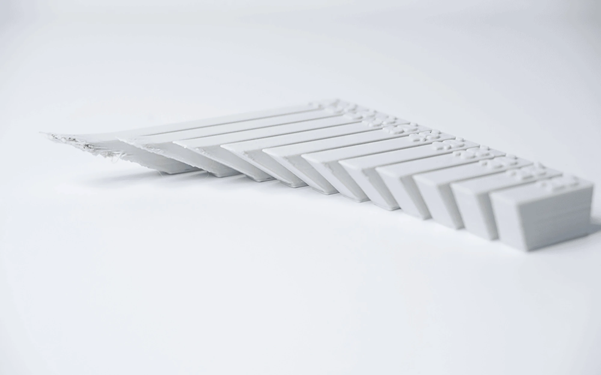
Warping
Something that is often easily overlooked while designing a 3D model is the fact that the materials used for 3D printing undertake physical change: they are melted, sintered or scanned with a laser and solidified. The heating and cooling of material can cause the parts to warp while printing.
Large, flat surfaces can be especially prone to warping. Warping can typically be avoided by using correct machine calibration and having adequate surface adhesion between your part and the print bed. Your Hub will be able to offer more advice on design techniques that can be used to minimize the likelihood of warping.
A good practice is to avoid large flat surfaces and add rounded corners to your 3D models.

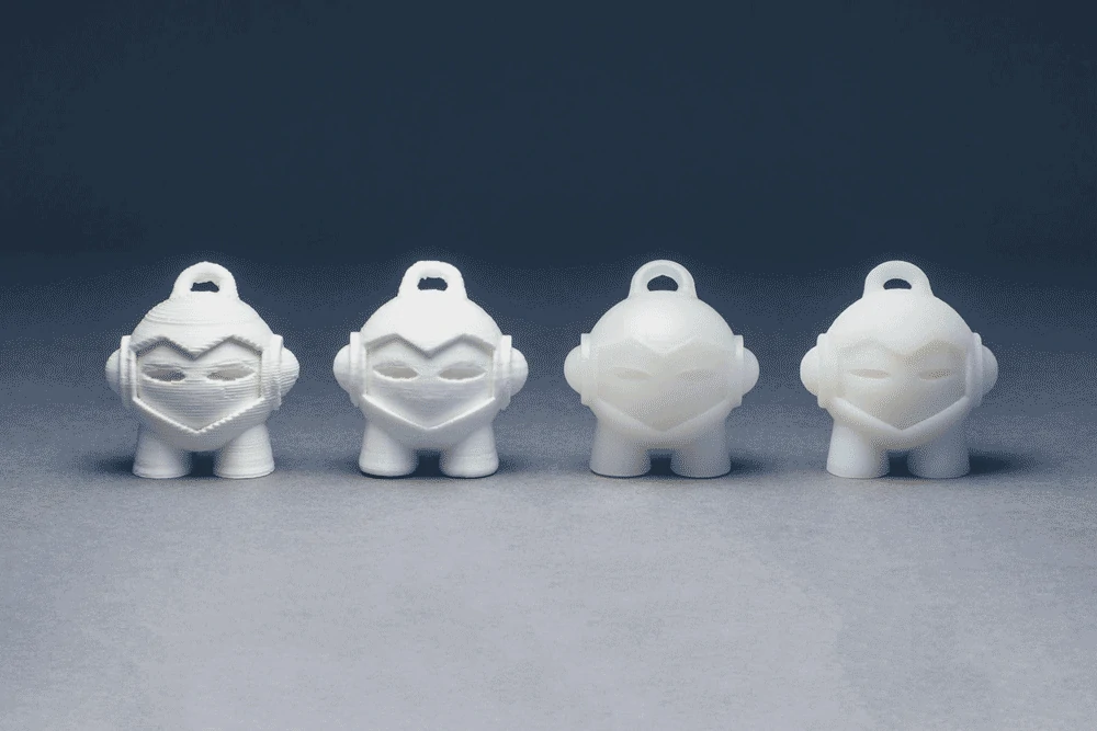
Level of detail
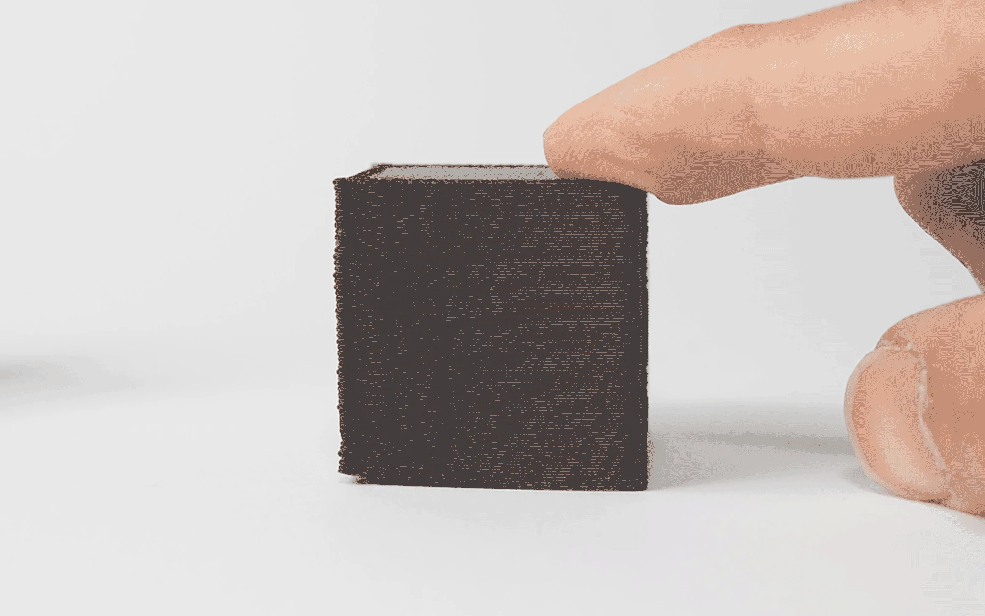
When you are creating a 3D model with intricate details, it is important to keep in mind what is the minimum feature size each 3D printing process can produce. The minimum level of detail is connected to the capabilities and mechanics of each 3D printing process and to the selected layer height.
The process and materials used will have an impact on the speed and cost of your print, so determining whether smaller details are critical to your model is an important design decision.

Rules of Thumb
Avoid overhangs in your design when possible, by using angles smaller than 45 degrees.
Add at least 0.8 mm wall thickness to your models.
Avoid large flat surfaces and use rounded corners to avoid warping.
Decide what is the minimum level of detail your models require and choose a 3D printing process accordingly.
Introduction
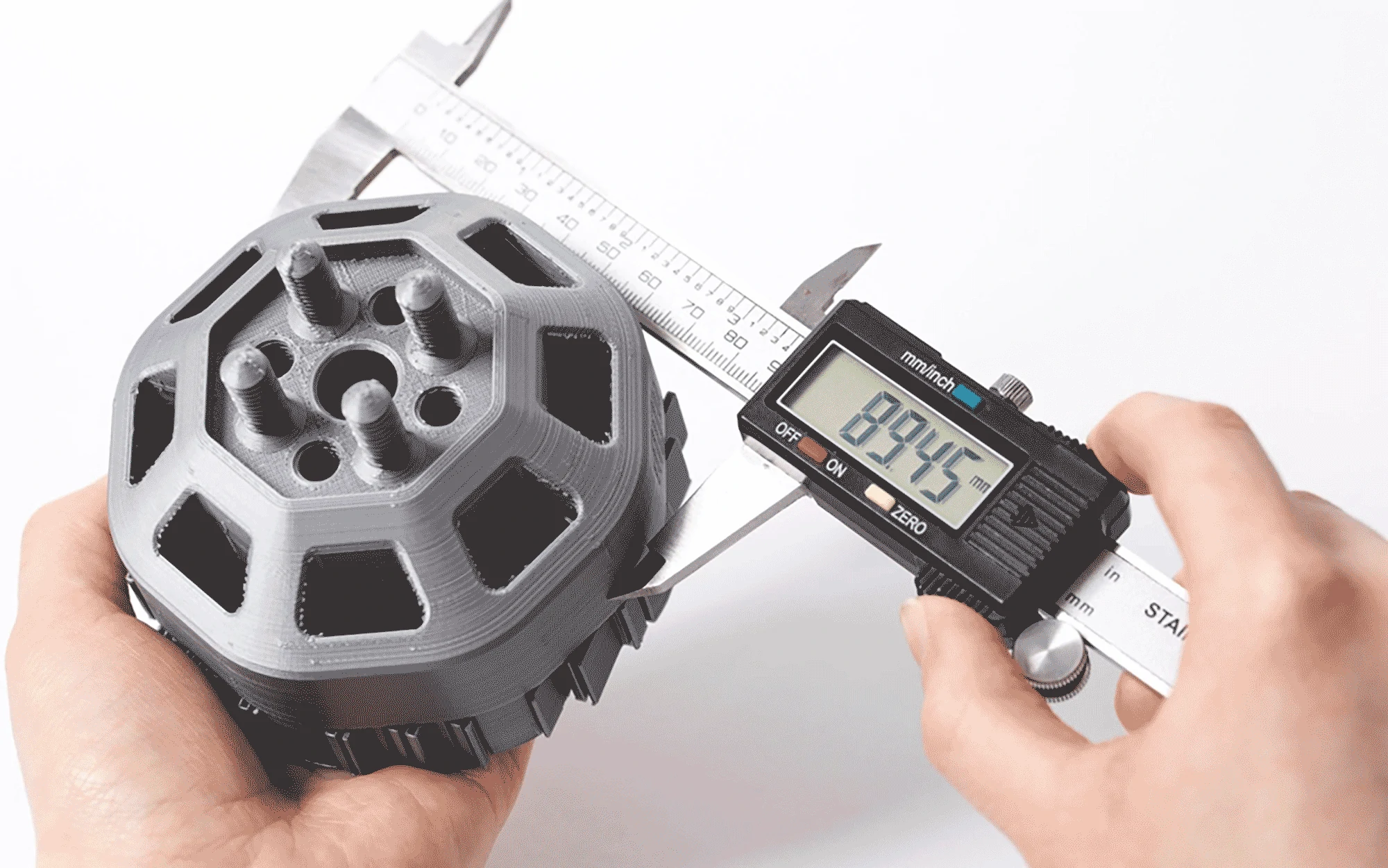
The aim of this article is to provide engineers and designers with a method for comparing the expected dimensional accuracy that can be obtained from 3D Printing technologies. While all technologies have strengths and weaknesses, the 2 most governing factors on whether a part will print to specifications are:
Design - The accuracy of printed a part depends heavily on the design. Variations in cooling and curing result in internal stresses that can lead to warping or shrinkage. 3D printing is not suited for flat surfaces or long thin unsupported features. Accuracy will also decrease as part sizes become larger.
Materials - Like design, accuracy also depends upon material. Often the accuracy of a part is sacrificed for the enhancement of a specific material property. For example, a standard SLA resin will produce more dimensionally accurate parts than flexible resin. For parts where high accuracy is critical, standard printing materials are recommended.

Accuracy variables
In order to help quantify the accuracy of a 3D printed part the following parameters will be used.
Dimensional accuracy - quantitative values from machine manufacturers and material suppliers that state the expected accuracy of parts. All tolerances stated are with respect to well designed parts on a well calibrated machines.
Warping or shrinkage - the likelihood a part will warp or shrink during the printing stage. This depends heavily on design however some processes produce parts that are inherently more at risk of warping or shrinking.
Support requirements - for many 3D printing technologies, the amount of support used will govern how accurately a surface or feature is printed. The downside to this is that support affects the surface finish of a part as it must be removed.
FDM
Fused deposition modeling (FDM) is best suited for low-cost prototyping, where form and fit are more important than function.FDM produces parts one layer at a time by extruding a thermoplastic onto a build plate.
For large parts, this can lead to big variations in temperature across the build platform. As different areas of the part cool at different rates internal stress cause the print to deform, leading to warping or shrinkage. Solutions like printing rafts, heated beds, and radii at sharp edges and corners can help to reduce this.
Differnet materials are more prone to warping than others. For example, ABS is known to be more susceptible to warping than PLA.
Dimensional tolerance
± 0.5% (lower limit: ± 0.5 mm) - desktop± 0.15% (lower limit: ± 0.2 mm) - industrial
Shrinkage/warping
Thermoplastics that require a higher print temperature are more at risk. Adding a radius on the bottom edge in contact with the build plate or a brim is recommended. Shrinkage usually occurs in the 0.2 - 1% range depending on material.
Support requirements
Essential to achieve an accurate part. Required for overhangs greater than 45 degrees.
SLA
SLA (stereolithography) printers use a laser to UV cure specific areas of a resin tank to form a solid part one cross-section at a time. These cured areas, however, are not at full strength until post-processing with UV. Because of this and the angle and orientations that SLA parts are typically printed at, sagging of unsupported spans can occur.
As one layer is built up at a time, this effect becomes cumulative leading to the dimensional discrepancies sometimes seen in tall SLA parts. Dimensional discrepancies can also occur because of the peeling process used by some SLA printers. The pulling force during the peeling process can cause the soft print to bend which again can accumulate as each layer is built up.
Resins that have higher flexural properties (less stiff) are at a greater risk of warping and may not be suitable for high accuracy applications.
Dimensional tolerance
± 0.5% (lower limit: ± 0.10 mm) - desktop± 0.15% (lower limit: ± 0.01 mm) - industrial
Shrinkage/warping
Likely for unsupported spans.
Support requirements
Essential to achieve an accurate part.
SLS
Selective laser sintering (SLS) produces parts with high accuracy and can print designs with complex geometry. A laser selectively sinters powder one layer at a time to form a solid part.
To restrict the likelihood of parts warping or shrinking during printing, SLS printers use heated build chambers that heat up the powder to just below the sintering temperature. This does still, however, result in temperature gradients in large SLS parts where the bottom of the part has cooled while the recently printed top layers remain at an elevated temperature. To further mitigate the likelihood of warping occurring parts are left in the powder to cool slowly (often for 50% of the total build time).
Dimensional tolerance
± 0.3% (lower limit: ± 0.3 mm)
Shrinkage/warping
Shrinkage usually occurs in the 2 - 3% range however most SLS print providers allow for this in the design.
Support requirements
Not required.
Metal 3D printing
Metal printing (specifically DMLS and SLM) use a laser to selectively sinter or melt metal powder to produce metal parts. Much like SLS, metal printing produces parts one layer at a time in a controlled, heated environment on industrial-sized machines. This layer-by-layer construction coupled with the very high temperatures involved in the process creates extreme thermal gradients, and the net effect is that stresses are built into the part.
As a result, metal printed parts are at a high risk of distorting or warping, meaning good design practices and part orientation are critical to achieving an accurate part. Unlike SLS, support structures are vital to minimize distortion of the part during production. Parts are also generally built upon a solid metal plate and need to be removed once the print process is complete. A sound understanding of the process is required along with solid and lattice support structures to keep the part securely attached to the print bed and stop it from detaching. Most parts are also stress relieved (via a heat treatment process) after they’re built and before removal from the build plate (doing so allows the crystalline structure to relax, preventing failure later).
Since the cost of metal 3D printed parts is high, simulations are often used to validate the accuracy of a design, before starting the print job.
Dimensional tolerance
± 0.1 mm
Shrinkage/warping
Parts at a high risk of shrinkage or warping. Bracing and support are used to help reduce the likelihood of this occurring.
Support requirements
Essential to achieve an accurate part.
Rules of Thumb
For the highest accuracy (and when budget is not a constraint), Material Jetting is the optimal solution.
For high accuracy, SLA is recommended for parts smaller than 1000 cm3 (10 x 10 x 10 cm), and SLS for parts with dimensions greater than 1000 cm3 (10 x 10 x 10 cm). Quick, cost-effective prototyping FDM is the best solution.